EN
EN
 English
 Español
 Français
 Português
 عربى
عربىWhat Should You Look for When Choosing a Straight Line Wire Drawing Machine for Low Carbon Steel?
Content
- 1 Why Machine Selection Matters for Low Carbon Steel Wire Drawing
- 2 Define Your Wire Specification Before Evaluating Machines
- 3 Number of Drawing Dies and Pass Schedule Design
- 4 Drawing Speed and Its Effect on Low Carbon Steel
- 5 Cooling System Requirements for Continuous Drawing
- 6 Lubrication System: Wet vs. Dry Drawing for Low Carbon Steel
- 7 Key Machine Specifications to Compare Across Suppliers
- 8 Drive System and Tension Control Considerations
- 9 After-Sales Support and Spare Parts Availability
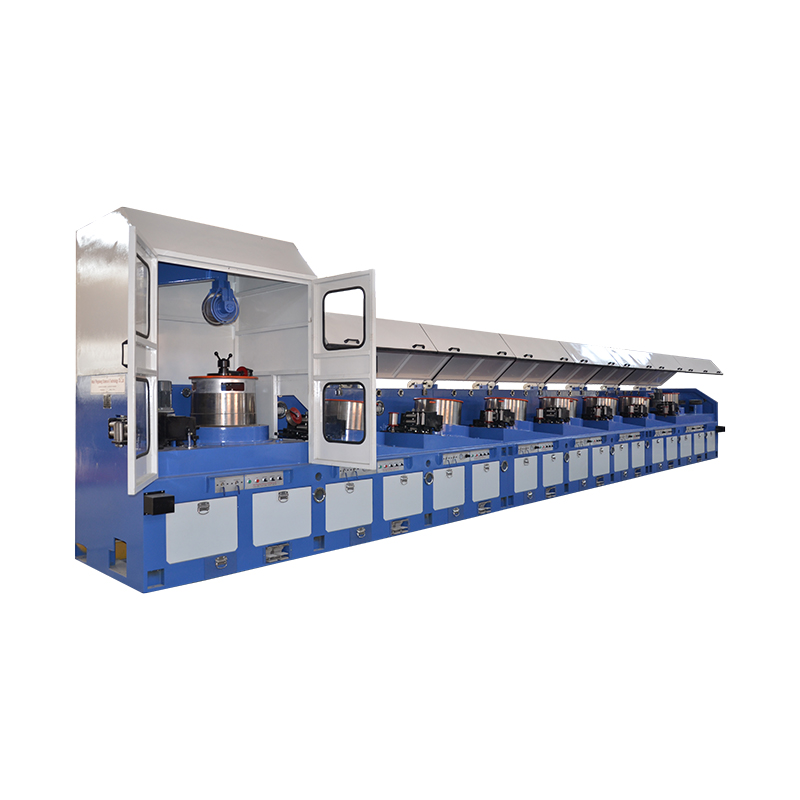
Why Machine Selection Matters for Low Carbon Steel Wire Drawing
Low carbon steel — typically defined as steel with a carbon content below 0.30% — is one of the most widely drawn wire materials in the world. Its relatively low yield strength and good ductility make it cooperative under deformation, but those same properties mean that process parameters must be managed carefully to avoid surface defects, excessive die wear, and inconsistent mechanical properties in the finished wire. Choosing the right straight line wire drawing machine for low carbon steel is not simply a matter of matching input and output diameter. It involves evaluating drawing speed, die pass schedule, cooling capacity, capstan design, and lubrication system in combination — because each factor influences the others, and a mismatch in any one area compromises the entire process.
Straight line machines are the standard configuration for medium and fine wire drawing of low carbon steel in continuous production. Unlike bull block or accumulating block machines, straight line machines pull the wire through each die in a true straight path between capstans, which gives precise tension control and consistent die entry angles. This configuration is particularly important for low carbon steel wire destined for galvanizing, welding wire production, or precision spring manufacturing, where dimensional consistency and surface quality over long coil lengths are non-negotiable.
Define Your Wire Specification Before Evaluating Machines
Before comparing machine specifications, you need a precise definition of what you are producing. The starting rod or coil diameter, the finished wire diameter, the required mechanical properties, and the intended downstream process all drive machine selection in ways that cannot be addressed after purchase. Low carbon steel wire for nail making has different requirements than wire for mesh welding or wire for PC strand precursor drawing — and a machine optimized for one application will produce suboptimal results in another.
At minimum, establish the following before approaching machine suppliers:
- Input diameter: The diameter of the incoming rod or wire, typically 5.5 mm to 8.0 mm for rod breakdown machines, or 1.5 mm to 4.0 mm for intermediate and finishing machines.
- Finished wire diameter: The target output diameter and its tolerance. Tighter tolerances require more precise capstan speed control and better die alignment.
- Total area reduction: The percentage reduction from input to output diameter. For low carbon steel, total reductions above 80–85% in a single machine pass may require intermediate annealing depending on the steel's initial properties.
- Required tensile strength: Work hardening during drawing increases tensile strength. If the finished wire must meet a specific strength range, the reduction schedule must be designed to achieve it, and the machine must be capable of executing that schedule.
- Production volume and coil weight: Target output in tons per day or month determines the required drawing speed and takeup capacity, which in turn affect motor sizing, cooling requirements, and machine footprint.
Number of Drawing Dies and Pass Schedule Design
The number of drawing dies on a straight line machine determines how the total area reduction is distributed across individual passes. Each die applies a partial reduction — typically between 15% and 25% per pass for low carbon steel — and the sum of these reductions achieves the total required reduction. A machine with more dies can distribute each reduction more gently, reducing die pressure, heat generation per pass, and the risk of wire breakage. However, more dies also means higher capital cost, greater machine length, and more complex speed synchronization between capstans.
For low carbon steel rod breakdown from 6.5 mm to approximately 2.0 mm, a 9-die to 13-die straight line machine is typical. For intermediate drawing from 2.0 mm to 0.8 mm, a 7-die to 11-die configuration is common. The exact number depends on the per-pass reduction you target. Using larger per-pass reductions reduces the number of dies needed but increases temperature rise in the wire at each pass — a concern for low carbon steel because excessive temperature can cause strain aging, particularly in aluminum-killed steels, which stiffens the wire and reduces ductility in ways that are not visible during drawing but cause problems in downstream forming.
Drawing Speed and Its Effect on Low Carbon Steel
Drawing speed — measured at the finished wire capstan — directly affects productivity, heat generation, lubrication film stability, and wire surface quality. For low carbon steel, practical drawing speeds on modern straight line machines range from 8 m/s to 25 m/s depending on wire diameter and die design. Finer wire diameters allow higher linear speeds because the reduced cross-section generates less absolute heat per unit time even when the surface velocity is high.
Higher speeds increase output but create two challenges specific to low carbon steel. First, the increased deformation rate raises the temperature of the wire at the die exit. Low carbon steel is sensitive to blue brittleness — a phenomenon occurring between approximately 200°C and 350°C where tensile strength increases but ductility drops sharply. If the wire temperature in intermediate passes enters this range, the risk of breakage at subsequent dies increases significantly, and the finished wire may fail elongation requirements. Second, higher speeds demand a lubrication system that can maintain a consistent film at the die entry under dynamic conditions — a wet drawing lubricant system with forced circulation and temperature control is essential above 12–15 m/s.
Cooling System Requirements for Continuous Drawing
Heat management is one of the most critical and often underspecified aspects of straight line machine selection for low carbon steel. Drawing generates heat through plastic deformation and friction at the die interface. In a multi-die straight line machine, this heat accumulates progressively if not removed between passes. The cooling system must extract enough heat from each capstan to keep the wire temperature at the next die entry within acceptable limits.
Capstan cooling in straight line machines is typically achieved through internal water circulation within hollow capstan drums. The cooling capacity required scales with wire speed, total reduction, and wire diameter. A machine drawing 2.5 mm low carbon steel at 15 m/s through a 12-die schedule may require a cooling water flow rate of 80–120 liters per minute across all capstans to maintain wire temperature below 150°C at each die entry. When evaluating machines, ask suppliers for the cooling capacity specification in kilowatts of heat removal, not just the water flow rate — flow rate without temperature differential data is meaningless as a performance specification.
Die cooling is equally important. Carbide dies for low carbon steel drawing should be cooled by immersion in the recirculating lubricant bath or by direct water jacket cooling around the die holder. Uncooled dies operating at high speed accumulate heat that softens the cobalt binder in tungsten carbide, dramatically accelerating die wear and causing dimensional drift in the finished wire diameter.
Lubrication System: Wet vs. Dry Drawing for Low Carbon Steel
Low carbon steel wire drawing is performed using either dry or wet lubrication, and the machine must be designed for the specific lubricant system you intend to use. The choice between them depends on wire diameter, drawing speed, and surface finish requirements.
Dry Drawing
Dry drawing uses solid lubricants — typically soap powder or calcium-based compounds — applied to the wire in a lubricant box before the die. It is standard for coarser wire diameters above approximately 1.5 mm and for lower-speed production. Dry drawing machines are simpler in construction, easier to clean between product changes, and generate less effluent. However, at high speeds or small diameters, solid lubricants cannot maintain a sufficient film at the die interface, leading to increased friction, higher wire temperature, and accelerated die wear.
Wet Drawing
Wet drawing submerges the dies and capstans in a continuously circulating lubricant emulsion — typically a soap or synthetic lubricant mixed with water. The lubricant simultaneously reduces friction at the die, cools the wire and die, and flushes away metal fines generated by the drawing process. Wet drawing is standard for fine wire below 1.5 mm and for high-speed production above 12 m/s. It requires a more complex machine with enclosed lubricant tanks, filtration, pH and concentration monitoring, and effluent treatment for disposal. For low carbon steel at production speeds above 15 m/s, wet drawing is effectively mandatory to achieve consistent wire quality and acceptable die life.
Key Machine Specifications to Compare Across Suppliers
When requesting quotations from machine manufacturers, the following specifications should be collected and compared in a consistent format to enable a meaningful evaluation:
| Specification | What to Ask For | Why It Matters |
| Number of dies | Total die count and per-pass reduction range | Determines flexibility of reduction schedule |
| Maximum drawing speed | Speed at finished wire capstan (m/s) | Sets productivity ceiling and cooling demand |
| Capstan cooling capacity | kW heat removal per capstan; total system | Limits wire temperature and prevents strain aging |
| Motor drive system | Individual AC inverter drives vs. line shaft | Affects tension control precision and energy use |
| Lubrication system type | Wet or dry; tank volume; filtration specification | Determines suitability for target speed and diameter |
| Takeup spooler capacity | Maximum coil or spool weight (kg) | Affects changeover frequency and downstream handling |
| Wire break detection | Sensor type and response time (ms) | Reduces downtime and protects dies on breakage |
Drive System and Tension Control Considerations
Modern straight line wire drawing machines use individual AC inverter drives on each capstan, allowing independent speed control at every drawing station. This is a significant practical advantage over older line-shaft or group-drive configurations, particularly for low carbon steel. Because low carbon steel work-hardens progressively through the drawing sequence, the speed ratio between successive capstans must change as the wire's elastic modulus and yield behavior evolve through the reduction schedule. Individual drives allow these ratios to be set and stored as programs for each wire product, enabling rapid changeover between different finished diameters without mechanical adjustment.
Tension control between dies is equally important for surface quality. Excessive back tension at any die entry increases the effective drawing stress, can trigger wire breakage, and leaves residual stress in the finished wire that causes coil springback problems in downstream processing. Insufficient back tension allows the wire to go slack between capstans, causing looping, surface marking, and inconsistent die entry angles. Specify machines with automatic tension monitoring and closed-loop control rather than fixed speed ratio systems, particularly if you are drawing multiple wire grades on the same machine.
After-Sales Support and Spare Parts Availability
A straight line wire drawing machine is a long-term capital investment with a typical service life of 15 to 25 years. The technical quality of the machine at the time of purchase is only part of the total cost of ownership. Spare parts availability, response time for technical support, and the supplier's ability to provide replacement components for control systems, drive units, and capstan seals over the machine's service life are equally important factors that are frequently underweighted in the initial purchasing decision.
Before committing to a supplier, request a full spare parts list with lead times and pricing for critical components — capstan bearings, die holders, lubricant pump seals, and inverter drive units. Confirm whether the machine uses proprietary control systems that require the original manufacturer for software support, or whether it uses standard industrial PLC and HMI platforms that can be serviced by third parties. For low carbon steel wire production targeting continuous multi-shift operation, an unplanned machine stoppage lasting more than 24 hours due to unavailable parts can negate months of cost savings achieved by selecting a lower-priced supplier at the outset.