
 EN
EN
 English
 Español
 Français
 Português
 عربى
عربىHow Does a Straight Line Wire Drawing Machine Work?
Content
- 1 What Is a Straight Line Wire Drawing Machine?
- 2 Core Components and How They Work Together
- 3 Advantages of the Straight Line Design
- 4 Typical Applications Across Industries
- 5 Key Specifications to Evaluate Before Purchasing
- 6 Maintenance Practices That Extend Machine Life
- 7 Optimizing Die Schedules for Better Results
- 8 Conclusion
In modern wire manufacturing, precision and efficiency are non-negotiable. Whether producing steel wire for construction, copper wire for electrical applications, or aluminum wire for aerospace components, the equipment used determines the final product's quality. Among the various types of wire drawing equipment, the straight line wire drawing machine stands out for its ability to handle large-diameter, high-strength wire with consistent accuracy. This article explores how these machines work, what makes them effective, and how to select the right configuration for your operation.
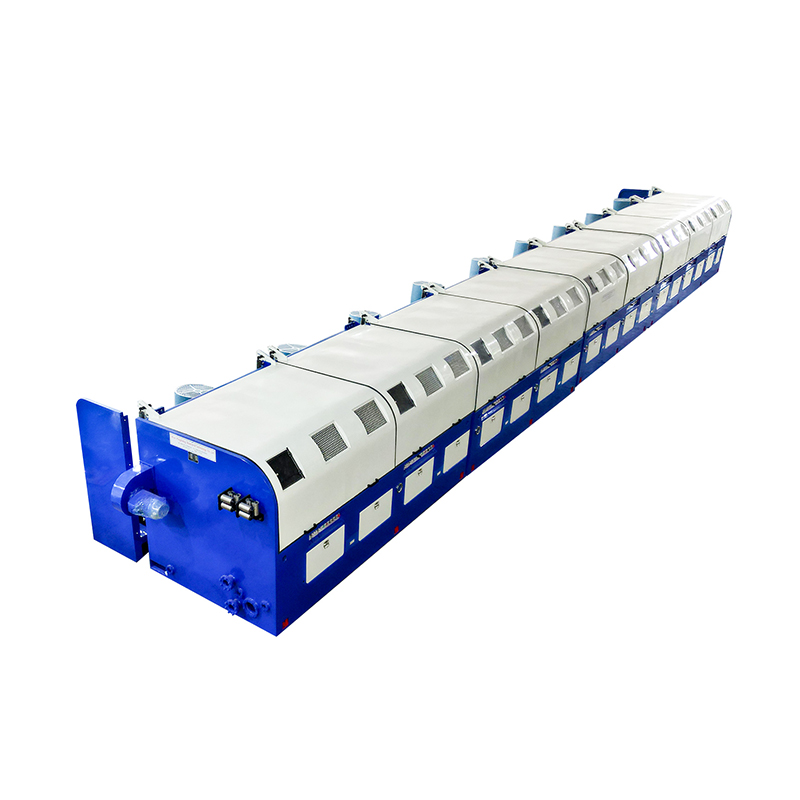
What Is a Straight Line Wire Drawing Machine?
A straight line wire drawing machine is an industrial device that reduces the diameter of wire or rod by pulling it through a series of progressively smaller dies arranged in a straight, linear configuration. Unlike the slip-type or non-slip drawing machines that use rotating capstans at angles, the straight line design aligns all drawing blocks and dies along a single horizontal axis. This arrangement minimizes torsional stress on the wire during the drawing process, making it particularly suitable for stiff, hard materials that cannot tolerate twisting.
The machine is commonly used for drawing stainless steel wire, spring steel, welding wire, and other high-carbon or alloy steel products. It can process wire diameters ranging from 1.0 mm up to 12 mm or more, depending on the model and configuration. The output is a wire with tighter dimensional tolerances, improved surface finish, and enhanced mechanical properties such as tensile strength and hardness.
Core Components and How They Work Together
Understanding the individual components of a straight line wire drawing machine helps clarify how the entire system delivers reliable performance. Each part plays a specific role in the drawing sequence.
Pay-Off Unit
The process begins at the pay-off unit, which holds the input coil or rod. A well-designed pay-off system maintains consistent tension as wire is fed into the machine. Most modern units feature active tension control to prevent slack or over-tension, both of which can cause wire breakage or die damage.
Drawing Dies
Dies are the heart of the drawing process. Each die features a precisely shaped hole through which the wire is pulled, compressing and elongating it to reduce diameter. Dies are typically made from tungsten carbide for standard applications or polycrystalline diamond (PCD) for fine wire or abrasive materials. Die angle, bearing length, and surface finish all influence wire quality and die lifespan.
Drawing Blocks (Capstans)
After passing through each die, the wire wraps around a drawing block that pulls it forward. In straight line machines, each block is powered independently or through a synchronized drive system. This allows individual speed adjustments to match the wire elongation at each reduction stage, preventing slippage and reducing heat buildup.
Lubrication System
Lubrication is critical for reducing friction between the wire and die surface. Most straight line machines use a wet lubrication system where drawing compound — typically an emulsion or soap-based fluid — is applied directly at each die box. Proper lubrication reduces die wear, improves surface quality, and lowers drawing force requirements significantly.
Take-Up Unit
Once the wire has passed through all drawing stages, it is collected on a spool or coil by the take-up unit. The take-up system maintains proper winding tension and layer consistency. For downstream processes such as coiling or cutting, a clean, uniform spool is essential.
Advantages of the Straight Line Design
The straight line configuration offers several advantages over alternative wire drawing setups, especially when dealing with demanding materials and tight tolerances.
- No wire twist: Because the wire travels in a straight path from die to die, there is no torsional deformation. This is critical for spring wire, welding wire, and other products where residual twist causes downstream problems.
- Suitable for large diameters: Straight line machines handle thick, stiff wire that would be difficult or impossible to guide through a curved or slip-type machine without cracking or breakage.
- High reduction ratios per pass: With the proper die schedule, a straight line machine can achieve greater total area reduction compared to other machine types in a single pass.
- Improved surface finish: Efficient lubrication delivery at each die, combined with reduced mechanical stress, produces a cleaner wire surface with fewer micro-cracks or surface defects.
- Easy maintenance access: The linear layout simplifies die changes, block inspections, and lubrication system servicing compared to more compact multi-block arrangements.
Typical Applications Across Industries
Straight line wire drawing machines are deployed across a wide range of industries where wire quality directly impacts product performance and safety.
| Industry | Wire Type | Typical Diameter Range |
| Construction & Concrete | PC steel wire, rebar tie wire | 3.0 – 12.0 mm |
| Automotive | Spring wire, tire bead wire | 1.0 – 6.0 mm |
| Welding Industry | MIG/TIG welding wire | 0.8 – 4.0 mm |
| Cable Manufacturing | Steel strand, armoring wire | 2.0 – 8.0 mm |
| Hardware & Fasteners | Nail wire, screw stock | 1.5 – 5.0 mm |
Key Specifications to Evaluate Before Purchasing
Selecting the right straight line wire drawing machine requires a thorough analysis of your production requirements. Choosing a machine that is underpowered or not designed for your material can result in frequent breakdowns, poor product quality, and high operating costs.
Number of Drawing Passes
Most straight line machines offer between 4 and 17 drawing passes. The number of passes determines the total reduction ratio achievable in a single run. For high-carbon steel, a lower reduction per pass is typically required to prevent work hardening and cracking, so more passes may be necessary to reach the target diameter.
Drive System Type
Machines may use a single-motor or multi-motor drive system. Single-motor systems are simpler and less expensive but offer less flexibility. Multi-motor systems with individual AC or DC drives allow precise speed synchronization at each block, which is critical for demanding materials and tight tolerances. Frequency inverter (VFD) control is now considered standard for modern machines.
Drawing Speed
Straight line machines generally operate at lower speeds than multi-slip machines, typically in the range of 2 to 20 meters per second at the final block, depending on wire diameter and material. Higher speed increases productivity but also generates more heat, which must be managed through effective cooling and lubrication systems.
Cooling System
Heat management directly affects wire metallurgy and die life. Look for machines with built-in block cooling (water-cooled capstans), die box temperature monitoring, and an efficient lubricant cooling circuit. Without adequate cooling, wire can develop undesirable microstructural changes, and dies will wear out prematurely.
Maintenance Practices That Extend Machine Life
Proper maintenance of a straight line wire drawing machine is essential to maintaining output quality and avoiding costly unplanned downtime. The following practices should be built into a regular maintenance schedule:
- Daily die inspection: Check each die for wear, surface cracking, or chipping. A worn die produces wire that is out of tolerance and can increase drawing force, stressing the entire drive system.
- Lubricant quality control: Monitor lubricant concentration, pH level, and contamination regularly. Degraded lubricant accelerates die wear and leaves deposits on the wire surface.
- Block surface inspection: Drawing blocks develop grooves over time that can mark the wire. Inspect and resurface blocks on a scheduled basis before visible damage occurs.
- Bearing and gearbox lubrication: Follow manufacturer intervals for grease replacement in bearings and oil changes in gearboxes. Neglecting drivetrain lubrication leads to premature failure of high-cost components.
- Electrical system checks: Inspect motor connections, drive parameters, and sensor calibration. Erratic speed control at any block can cause wire breaks and product defects.
Optimizing Die Schedules for Better Results
A die schedule defines the sequence of die sizes used to reduce the wire from input diameter to final diameter. Poor die scheduling is a common cause of wire breakage, inconsistent mechanical properties, and excessive die wear. The goal is to distribute the reduction evenly across all passes while keeping the strain per pass within safe limits for the material being drawn.
For high-carbon steel wire, a reduction per pass of 15% to 20% area reduction is typical. For softer materials like low-carbon steel or copper, reductions of up to 25% to 30% per pass may be achievable. Engineering your die schedule around these limits — and verifying them through tensile testing and elongation checks — results in lower wire break rates, longer die life, and more consistent finished wire properties across production runs.
Conclusion
A straight line wire drawing machine is a precision production tool that demands careful selection, proper setup, and disciplined maintenance to deliver its full value. Its ability to process high-strength, large-diameter wire without introducing torsional defects makes it indispensable in sectors where wire quality is directly linked to end-product safety and performance. By understanding the machine's core components, evaluating specifications against your material and output requirements, and following structured maintenance routines, manufacturers can achieve consistent quality, reduced operating costs, and long equipment service life.


