
 EN
EN
 English
 Español
 Français
 Português
 عربى
عربى
How Does a Straight Line Wire Drawing Machine Improve Wire Quality?
Content
- 1 What a Straight Line Wire Drawing Machine Does
- 2 Core Components and Their Functions
- 3 Typical Wire Materials and Diameter Ranges
- 4 Advantages Over Bull Block Drawing Machines
- 5 Factors That Affect Drawing Quality
- 6 Maintenance Practices That Extend Machine Life
- 7 Choosing the Right Machine for Your Production Needs
What a Straight Line Wire Drawing Machine Does
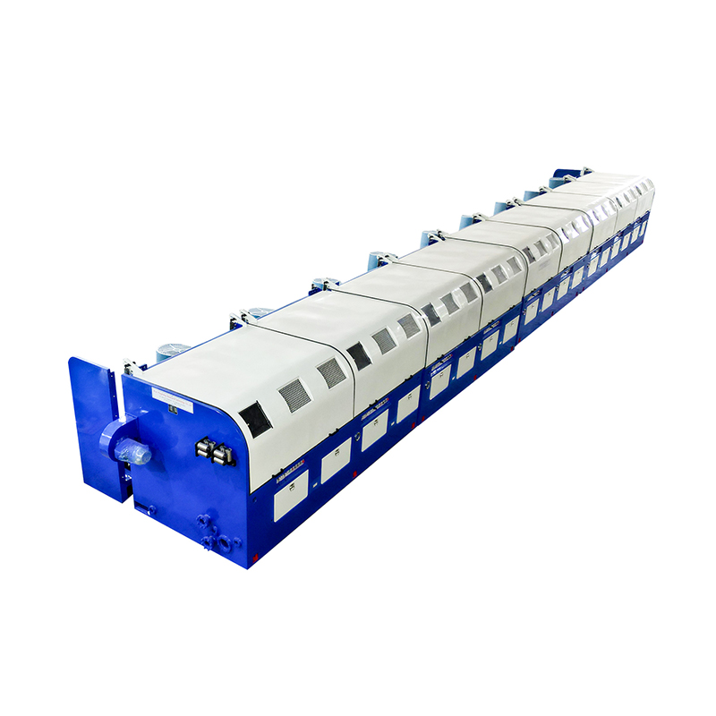
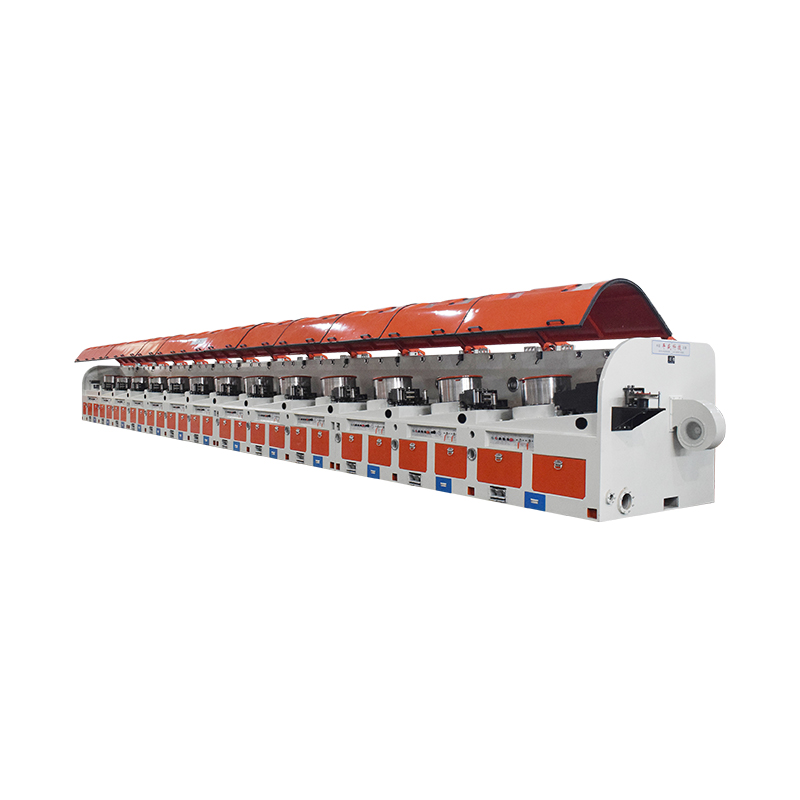
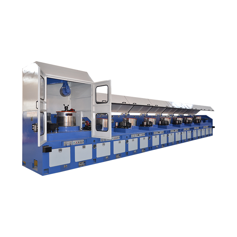
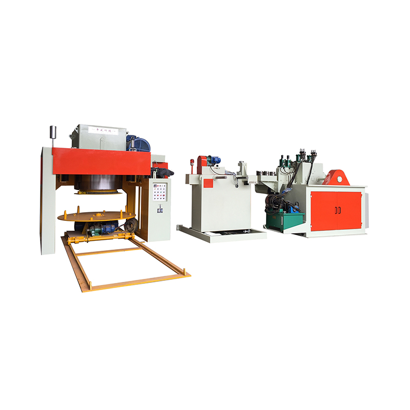
A straight line wire drawing machine reduces the diameter of a metal wire by pulling it through a series of dies arranged in a single straight path, rather than around a rotating drum as in a bull block or cone-type machine. Each die progressively reduces the wire's cross-section while increasing its length, and because the wire travels in a straight line rather than wrapping around capstans, the process generates less internal stress and produces a more uniform surface finish. This design is widely used for medium to large diameter wire, including applications where mechanical properties and surface consistency are critical.
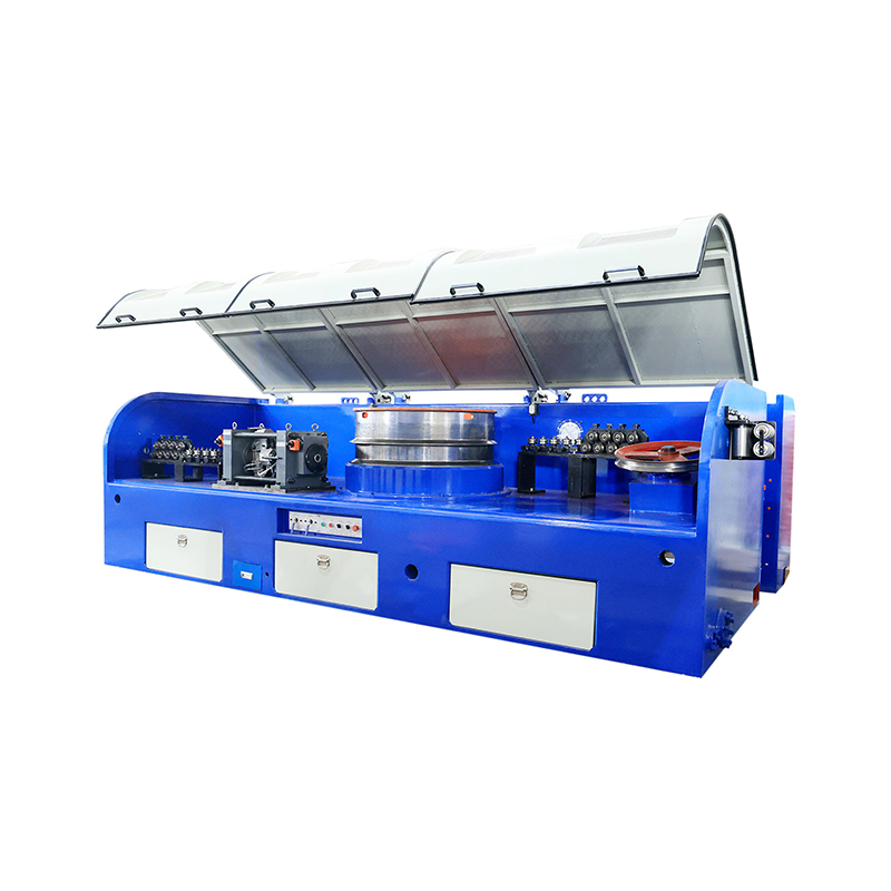
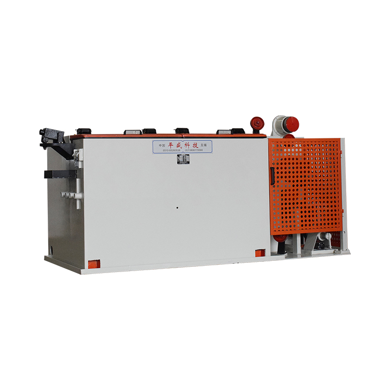
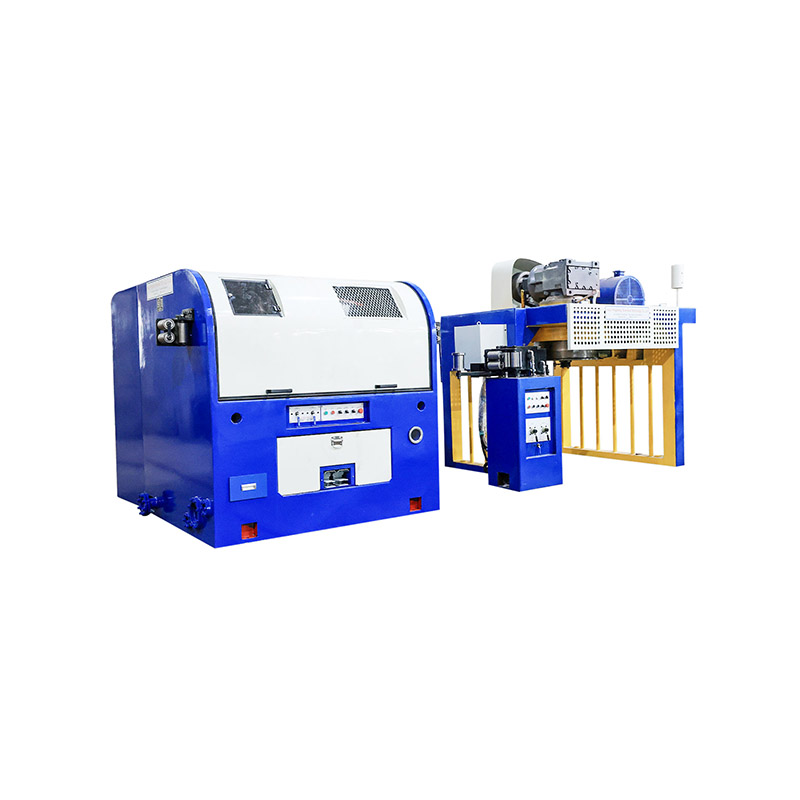
The machine typically consists of a pay-off unit that feeds the raw wire rod, a series of die boxes with tungsten carbide or polycrystalline diamond dies, a pulling mechanism that draws the wire through each die at controlled speed, and a take-up system that coils the finished wire onto a spool or reel. Between dies, the wire often passes through cooling and lubrication systems that prevent overheating and reduce friction, both of which directly affect die life and final wire quality.
Core Components and Their Functions
Understanding the function of each major component helps operators diagnose issues and maintain consistent output quality over long production runs.
Pay-off and Accumulator System
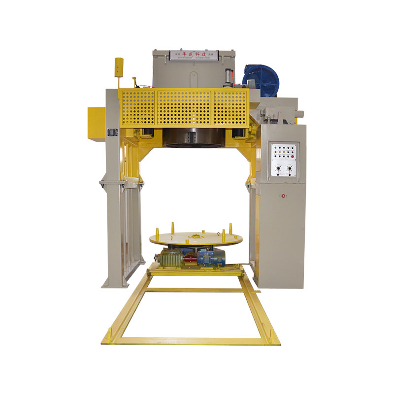
The pay-off unit unwinds the incoming wire rod at a controlled tension, while an accumulator buffers wire supply so the drawing process can continue uninterrupted during coil changes. Consistent pay-off tension is essential, since fluctuations can introduce diameter variation downstream.
Die Boxes and Die Sequence
Wire passes through multiple dies arranged in decreasing order of aperture size. Each die box houses a die along with lubricant to reduce friction and cool the wire during deformation. The number of dies and the reduction ratio at each stage are calculated based on the material's ductility to avoid excessive work hardening or wire breakage.
Capstan and Pulling Mechanism
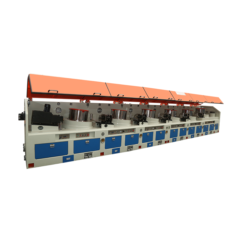
Unlike bull block machines, straight line drawing machines use a series of capstans or direct pulling wheels positioned in line with the wire path. This reduces bending stress on the wire and is particularly beneficial for wires that are prone to surface cracking or that require tight straightness tolerances.
Take-up and Spooling System
The finished wire is wound onto spools or reels at the end of the line. Precision layer winding at this stage prevents tangling and ensures the wire can be unwound smoothly during downstream processing, such as further drawing, coating, or fabrication.
Typical Wire Materials and Diameter Ranges
Straight line wire drawing machines are configured differently depending on the material being processed and the target output diameter. The table below outlines general ranges used across common industrial setups.
| Material | Input Diameter | Output Diameter | Common End Use |
| Low Carbon Steel | 5.5-8 mm | 1.0-4.0 mm | Fencing, mesh, nails |
| Stainless Steel | 4-6 mm | 0.5-3.0 mm | Springs, medical components |
| Copper | 8-12 mm | 1.0-5.0 mm | Electrical cabling, busbars |
| Aluminum | 6-10 mm | 1.5-6.0 mm | Overhead conductors, welding wire |
Advantages Over Bull Block Drawing Machines
Buyers evaluating wire drawing equipment often compare straight line machines to bull block or drum-type machines. Each has strengths, but the straight line design offers several practical advantages for specific production goals.
- Reduced bending stress on the wire, which lowers the risk of surface cracks in brittle or hard-drawn materials.
- Better dimensional accuracy and straightness, which is important for wire used in precision springs or medical devices.
- Easier handling of larger diameter wire that would be difficult to wrap around a capstan drum.
- More consistent cooling and lubrication delivery across each drawing stage, extending die life.
Factors That Affect Drawing Quality
Achieving consistent wire diameter, surface finish, and mechanical properties depends on controlling several interrelated variables throughout the drawing process.
- Die material and condition, since worn or improperly finished dies cause surface scoring and diameter drift.
- Lubricant type and application rate, which directly affect friction, heat buildup, and die wear.
- Drawing speed, since excessive speed can generate heat that alters the wire's metallurgical properties.
- Reduction ratio per pass, as overly aggressive reductions increase the likelihood of wire breakage.
- Annealing between passes for materials that work-harden quickly, restoring ductility before further drawing.
Maintenance Practices That Extend Machine Life
Routine maintenance keeps a straight line wire drawing machine running efficiently and reduces unplanned downtime. Operators should inspect dies regularly for wear patterns, since even minor surface degradation can translate into visible defects on the finished wire. Lubrication systems should be checked for contamination or depletion, as dirty or insufficient lubricant accelerates die wear and increases the risk of wire breaks. Capstans and pulling wheels should be examined for surface wear or misalignment, since uneven wire tension across passes can lead to inconsistent diameter control. Establishing a documented maintenance schedule, including die replacement intervals based on production volume, helps manufacturers maintain consistent quality while minimizing tooling costs over time.
Choosing the Right Machine for Your Production Needs
Selecting a straight line wire drawing machine requires matching machine specifications to the material type, target diameter range, and expected production volume. Buyers should evaluate the number of drawing dies, maximum line speed, motor power, and available cooling and lubrication capacity relative to their production goals. It is also worth confirming whether the machine includes integrated annealing capability, which can reduce the need for separate processing steps when working with materials that require intermediate softening. Consulting with equipment suppliers about material-specific configurations, and requesting performance data from similar installations, can help ensure the selected machine delivers the throughput and quality consistency required for long-term production.