
 EN
EN
 English
 Español
 Français
 Português
 عربى
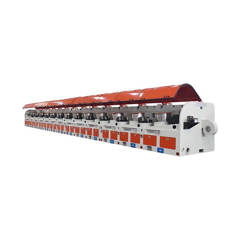
عربىHow Does a High Speed Multi Block Straight Line Wire Drawing Machine Work?
Content
- 1 What Is Multi Block Straight Line Wire Drawing?
- 2 How the High Speed Drawing Process Works Step by Step
- 3 Key Components and Their Engineering Functions
- 4 Performance Specifications and Production Capabilities
- 5 Advantages Over Other Wire Drawing Machine Configurations
- 6 Typical Industry Applications for Straight Line Drawn Wire
- 7 What to Evaluate When Selecting a High Speed Multi Block Machine
What Is Multi Block Straight Line Wire Drawing?
Multi block straight line wire drawing is a metal forming process in which a wire or rod feedstock is progressively reduced in diameter by being pulled through a series of hardened dies arranged in a straight, linear configuration. Each die in the sequence reduces the wire's cross-sectional area by a controlled percentage — a value known as the reduction ratio or area reduction — while increasing the wire's length proportionally to conserve volume. The term "multi block" refers to the multiple drawing blocks — motorized capstans or drums — positioned between successive dies that grip the wire and provide the pulling force needed to draw it through each die. Unlike accumulation-type or coil-to-coil drawing machines, where the wire coils around each capstan multiple times before proceeding to the next die, straight line machines feed the wire in a single, direct path from entry to exit without any lateral deviation or coiling at intermediate stages.
The straight line configuration is specifically advantageous for materials and wire sizes where coiling at intermediate stages would cause unacceptable work hardening, surface damage, or dimensional inconsistency. Hard materials such as high-carbon steel, stainless steel, copper alloys, and titanium wire benefit significantly from the absence of bending and straightening cycles that accumulation drawing machines impose between each die pass. The result is a finished wire with more uniform mechanical properties along its length, better dimensional accuracy, and superior surface quality — all attributes that are critical in demanding end uses such as automotive wire forms, welding wire, spring wire, and precision instrument wire.
How the High Speed Drawing Process Works Step by Step
Understanding the sequence of operations in a high speed multi block straight line wire drawing machine clarifies why each component in the system must be precisely engineered and synchronized. The process begins at the pay-off station, where the input rod or wire coil is mounted on a motorized unreeler or rotary pay-off that feeds material into the machine at a controlled tension. Consistent pay-off tension is essential because fluctuations in entry tension propagate through the entire drawing sequence and can cause wire breakage or diameter variation at the final die exit.
From the pay-off, the wire enters the first drawing die — a precision-machined insert made from tungsten carbide or polycrystalline diamond, housed in a robust steel casing. The die's conical entry angle, working zone geometry, and exit bearing zone are engineered to minimize friction, control material flow, and produce a smooth, work-hardened surface on the drawn wire. The wire is gripped by the first drawing block immediately after the die and pulled through at the speed determined by the block's rotational velocity and drum diameter. Between each successive die-and-block pair, the wire travels in a straight line supported by precision guide rollers that prevent sagging or lateral movement at high speeds.
Each drawing block runs at a slightly higher surface speed than the previous one — a relationship called the speed cascade — to account for the elongation of the wire as its diameter decreases. The speed cascade ratio between adjacent blocks must precisely match the area reduction at each die: if the ratio is too low, the wire goes slack between blocks and loses tension; if it is too high, the wire is stretched excessively, risking breakage or excessive work hardening between die passes. In modern high speed machines, this speed matching is maintained automatically by independent AC vector drives or servo drives on each block, controlled by a central PLC that monitors drawing tension and adjusts block speeds in real time to maintain consistent inter-block wire tension throughout the production run.
Key Components and Their Engineering Functions
The performance of a high speed multi block straight line wire drawing machine depends on the precision and reliability of each of its core mechanical and electrical subsystems. A failure or performance degradation in any single component propagates immediately to product quality and line throughput.
Drawing Dies
The drawing die is the heart of the wire drawing process. Modern high speed machines use dies with tungsten carbide nibs for steel and copper alloy wire, and polycrystalline diamond (PCD) or natural diamond nibs for fine wire, non-ferrous metals, and applications requiring the longest possible die life between changes. Die geometry — specifically the approach angle (typically 6° to 12° semi-angle), bearing length, and back relief — is selected based on the wire material, lubrication system, and reduction ratio at each pass. In high speed applications, die wear rate is accelerated by the elevated contact pressures and temperatures generated at drawing speeds above 20 m/s, making die material selection and lubrication system design critical factors in determining cost-per-ton of production.
Drawing Blocks and Drive System
The drawing blocks — also called capstans or bull blocks — are hardened steel or cast iron drums that grip the wire after each die and provide the pulling force for the next drawing step. In straight line machines, the wire makes only a partial wrap around each block — typically 180° to 270° — rather than the multiple wraps used in accumulation machines, which limits the contact time between wire and block surface and reduces the heat transferred to the block from the hot drawn wire. Block surface hardness and surface finish are critical: a rough or worn block surface causes surface marking on the wire, while inadequate hardness leads to rapid block wear that changes the effective drum diameter and disrupts the speed cascade calibration. Each block is driven by an independent variable-speed motor through a precision gearbox, with the drive control system maintaining speed accuracy within ±0.1% to ensure consistent inter-block tension.
Lubrication and Cooling System
High speed wire drawing generates substantial heat through plastic deformation of the wire and friction at the die interface. Without effective lubrication and cooling, die life collapses, wire surface quality deteriorates, and the elevated wire temperature entering each successive die causes uncontrolled work hardening that risks wire breakage. Wet drawing systems — in which liquid lubricant (typically a soap emulsion, synthetic drawing compound, or oil-in-water emulsion at concentrations of 3% to 10%) floods the die entry zone — are standard for copper, aluminum, and stainless steel wire drawing at high speeds. The lubricant simultaneously reduces die friction, carries heat away from the die and wire surface, and acts as a carrier for the extreme pressure additives that protect the die nib under high contact stress. Die boxes are typically cooled by recirculated water jackets, with chilled water systems maintaining die box temperature below 40°C even at production speeds above 30 m/s.
Tension Control and PLC Automation
Maintaining consistent wire tension between each die-block pair is the most technically demanding control challenge in high speed multi block drawing. Inter-block tension is monitored by dancer rollers or load cell systems that measure the wire deflection or force continuously and feed this data to the drive control system. The PLC adjusts individual block speeds within milliseconds to correct tension deviations caused by material property variations in the incoming wire, die wear, or lubricant film changes. Advanced machines also monitor and log drawing force data at each die position, enabling process engineers to detect die wear trends, identify material inconsistency in incoming rod coils, and optimize reduction schedules without interrupting production.
Performance Specifications and Production Capabilities
High speed multi block straight line wire drawing machines are specified across a wide range of wire diameters, drawing speeds, and installed power levels depending on the target wire product and material. The following table summarizes typical performance parameters for machines across the main market segments.
| Application Segment | Wire Diameter Range | Max Exit Speed | Number of Blocks | Typical Materials |
| Medium wire (coarse) | 3.0 – 8.0 mm | 8 – 15 m/s | 4 – 8 | Low/high carbon steel, stainless |
| Medium wire (fine) | 1.0 – 3.0 mm | 15 – 25 m/s | 6 – 12 | Spring steel, welding wire, copper |
| Fine wire | 0.3 – 1.0 mm | 25 – 40 m/s | 10 – 16 | Copper alloys, stainless, titanium |
| Very fine wire | 0.05 – 0.3 mm | 40 – 100+ m/s | 16 – 25 | Copper, gold, aluminum bonding wire |
Installed motor power on high speed multi block straight line machines scales significantly with wire size and drawing speed. Machines for medium wire typically have total installed drive power of 50 to 200 kW, while high speed fine wire machines may require 300 to 800 kW of installed power to maintain the required tension cascade at exit speeds above 40 m/s. Energy efficiency is therefore a meaningful operating cost factor, and modern machines incorporate regenerative braking systems on the drawing blocks that recover kinetic energy during deceleration and tension corrections, reducing net energy consumption by 10 to 20 percent compared to non-regenerative drive systems.
Advantages Over Other Wire Drawing Machine Configurations
The high speed multi block straight line configuration offers a distinct set of technical and operational advantages over alternative wire drawing machine types — particularly accumulation drawing machines and single-die drawing machines — that make it the preferred choice in specific production scenarios.
- Superior wire straightness: Because the wire is never coiled around intermediate capstans, it exits the machine with significantly better straightness than wire produced on accumulation machines. This is critical for applications such as spring wire, electrode wire, and precision instrument wire where residual curl causes downstream processing problems.
- Consistent mechanical properties along the wire length: The absence of bending and reverse-bending cycles between die passes means that work hardening accumulates uniformly along the wire, resulting in more consistent tensile strength, yield strength, and elongation values from the beginning to the end of each coil — a quality advantage that is particularly significant for automotive and aerospace wire applications.
- Compatibility with hard and brittle materials: High-carbon steel, stainless steel, titanium, and hard copper alloys that are prone to cracking or surface damage when bent over small radii at intermediate drawing stages can be processed reliably on straight line machines where bending is eliminated between passes.
- Higher achievable drawing speeds: The direct linear wire path allows drawing speeds significantly higher than those achievable in accumulation machines of equivalent die count, because there is no limitation imposed by the dynamics of wire coiling and unwinding at each intermediate capstan. This translates directly to higher production throughput per machine.
- Reduced surface marking and oxidation: The minimal contact between the wire and machine components between die passes reduces the risk of surface scratching and, in combination with the rapid transit time through the machine, limits the exposure of freshly drawn wire surface to atmospheric oxidation — an important quality factor for bright finish and electroplated wire products.
Typical Industry Applications for Straight Line Drawn Wire
The wire produced on high speed multi block straight line machines serves a diverse range of industrial end uses, where the superior dimensional accuracy, surface quality, and mechanical property consistency of straight line drawn wire justify the higher machine capital cost compared to simpler drawing configurations.
- Welding wire and electrode wire: MIG, TIG, and submerged arc welding wire requires extremely tight diameter tolerances — typically ±0.01 mm on a 1.2 mm diameter wire — and a smooth, consistent surface to ensure stable arc characteristics and reliable feeding through welding torch liners. High speed straight line drawing machines are the standard production method for these demanding specifications.
- Automotive wire forms and springs: High-carbon steel spring wire and valve spring wire for automotive engines must meet stringent tensile strength and fatigue life requirements that depend on uniform work hardening and freedom from surface defects. Straight line drawing is specified for these critical safety components by most automotive OEM wire specifications.
- Stainless steel wire for medical devices: Guide wires, surgical sutures, and medical implant wire made from austenitic stainless steel or nitinol require exceptional dimensional precision, surface cleanliness, and consistent mechanical properties that only straight line drawing at controlled speeds can reliably deliver at production scale.
- Copper magnet wire for electric motors: Fine copper wire for motor windings and transformer coils requires a perfectly round, smooth cross-section and consistent electrical conductivity along its full length. High speed straight line drawing machines with diamond dies and precision tension control are the preferred production route for fine magnet wire down to 0.05 mm diameter.
- PC strand and prestressed concrete wire: High-strength steel wire for prestressed concrete applications requires the maximum achievable tensile strength consistent with adequate ductility — a balance that demands precise control of reduction ratios and inter-pass tension that only multi block straight line machines can reliably maintain across the full production run.
What to Evaluate When Selecting a High Speed Multi Block Machine
Procuring a high speed multi block straight line wire drawing machine represents a significant capital investment, and selecting the right machine configuration requires a thorough assessment of both current production requirements and anticipated future product range. The following factors should be systematically evaluated before committing to a specification.
- Wire diameter range and material: Confirm that the machine's die holder dimensions, block diameters, drive torque ratings, and lubrication system design are compatible with the full range of wire sizes and materials you intend to process — both now and in foreseeable future product development. A machine undersized for your hardest material or smallest target diameter will create an immediate production bottleneck.
- Number of drawing passes and reduction schedule: The number of die-block pairs required depends on the total area reduction from input rod to finished wire diameter and the maximum reduction per pass achievable without wire breakage for the target material. Calculate the required number of passes using the total reduction ratio and typical per-pass reductions of 15% to 25% for steel or 20% to 30% for copper alloys before specifying the machine block count.
- Drive system technology: Modern machines with fully independent AC vector drives or servo drives on each block offer significantly better tension control, faster response to wire breakage events, and more flexible speed cascade adjustment than older machines with mechanical gearbox-coupled drive systems. The drive system's ability to maintain tension accuracy at maximum speed is the primary determinant of wire diameter consistency and breakage rate in production.
- Lubrication system capacity and filtration: Verify that the lubricant tank capacity, pump flow rate, filtration system, and cooling capacity are sized for continuous operation at maximum drawing speed. Inadequate lubricant cooling causes progressive lubricant degradation during a production shift, leading to increasing die temperatures, rising wire breakage rates, and declining surface quality as the shift progresses.
- After-sales support and spare parts availability: High speed drawing machines require periodic replacement of drawing dies, drawing block surface refurbishment, drive component maintenance, and occasional structural repairs. Confirm that the machine supplier maintains a local service organization, holds critical spare parts in regional stock, and can provide remote diagnostics support to minimize unplanned downtime in a production environment where machine availability directly determines monthly output.


