
 EN
EN
 English
 Español
 Français
 Português
 عربى
عربىWhat Is a Straight Line Wire Drawing Machine and How Does It Improve Wire Production Efficiency?
Content
- 1 What Is a Straight Line Wire Drawing Machine?
- 2 Core Components and Their Functions
- 3 Advantages of Straight Line Configuration Over Other Drawing Machine Types
- 4 Wire Materials and Product Types Commonly Processed
- 5 Machine Configurations and Drawing Speed Ranges
- 6 Key Selection Criteria When Choosing a Straight Line Wire Drawing Machine
- 7 Maintenance Practices That Extend Machine Service Life
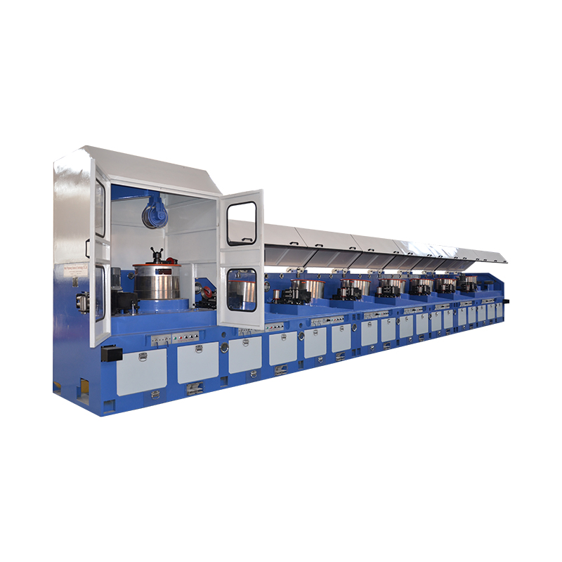
What Is a Straight Line Wire Drawing Machine?
A straight line wire drawing machine is an industrial metalworking system designed to reduce the cross-sectional diameter of wire rod or coiled wire by pulling it through a series of progressively smaller dies arranged in a straight, linear configuration. Unlike bull block or cone-type drawing machines where wire wraps around rotating drums or capstans in a circular path, the straight line design maintains the wire in a fundamentally linear trajectory throughout the drawing process. This geometric arrangement gives the machine its name and delivers a distinct set of production advantages that make it particularly well-suited to drawing medium and large diameter wire, as well as materials that are sensitive to bending stress or surface damage from repeated contact with curved surfaces.
The fundamental principle behind all wire drawing is plastic deformation: the wire is pulled through a die with an opening smaller than the wire's incoming diameter, forcing the metal to elongate and reduce in cross-section while increasing in length. In a straight line machine, this process is repeated through multiple drawing stages — typically between 4 and 17 passes depending on the degree of reduction required — with each stage progressively reducing the wire diameter by a controlled percentage known as the reduction ratio per pass. The accumulated reduction across all passes transforms the incoming wire rod, typically in the range of 5.5 mm to 14 mm diameter, into finished wire of the target specification, which may range from 1.0 mm to 8.0 mm depending on the machine configuration and product requirements.
Core Components and Their Functions
Understanding the mechanical architecture of a straight line wire drawing machine is essential for operators, maintenance engineers, and procurement managers evaluating equipment for specific production requirements. Each major subsystem performs a distinct and interdependent role in the drawing process.
Drawing Dies
The drawing die is the primary tooling element and consists of a precisely engineered aperture through which the wire is pulled. Dies are manufactured from tungsten carbide for standard steel and non-ferrous wire applications, or from polycrystalline diamond (PCD) for fine wire and abrasive materials requiring superior wear resistance and surface finish. Each die has four functional zones: the entry bell that guides wire into the die, the approach angle that begins the reduction, the bearing zone that defines the final wire diameter, and the back relief that allows the wire to exit without scoring. Die geometry — particularly the approach half-angle, typically between 6° and 12° for steel wire — directly affects drawing force, wire surface quality, die wear rate, and the heat generated during deformation. In a multi-pass straight line machine, the die sequence is designed so that each successive die produces a controlled area reduction, with individual pass reductions commonly ranging from 15% to 25% of cross-sectional area.
Drawing Capstans or Blocks
Between each drawing die, a powered capstan — also called a drawing block or drawing drum — grips and advances the wire, providing the pulling force required to draw the wire through the preceding die. In a straight line machine, these capstans are typically arranged horizontally along the machine's longitudinal axis, with each capstan's peripheral speed precisely synchronized to the wire's elongated exit velocity from the die it serves. Speed synchronization is critical: if a capstan runs too fast relative to the wire's elongation rate, excessive back tension is applied to the die, increasing die wear and the risk of wire breakage; if it runs too slow, wire accumulates between stages and disrupts the continuous drawing process. Modern straight line machines use individual AC or DC motor drives with closed-loop speed control systems — often managed by a central programmable logic controller (PLC) — to maintain precise inter-stage tension throughout the drawing sequence.
Lubrication System
Lubrication is indispensable in wire drawing to reduce die wear, lower drawing force, control wire temperature, and achieve acceptable surface finish on the drawn wire. Straight line machines employ either dry lubrication — using powdered soap or lime-based compounds that coat the wire surface before it enters each die — or wet lubrication, where the wire and dies are continuously flooded with an aqueous emulsion or neat oil lubricant circulated through a closed filtration and cooling system. Wet lubrication is standard for fine and medium wire drawing applications requiring tight surface finish control and high drawing speeds. The lubricant also serves as a coolant, removing the substantial heat generated by plastic deformation and friction at the die interface. Effective thermal management through the lubrication system is essential for maintaining consistent wire mechanical properties and preventing premature die failure from thermal shock.
Pay-Off and Take-Up Systems
At the entry end of the machine, a pay-off unit — either a static cradle, rotating coil stand, or powered de-coiler — feeds incoming wire rod or coiled wire into the first drawing stage at a controlled, consistent rate that prevents slack or excessive tension in the feed zone. At the exit end, a take-up unit coils or spools the finished drawn wire onto reels, spools, or coil baskets at a speed precisely matched to the final drawing stage's output velocity. For continuous production without interruption at coil changes, modern machines are equipped with accumulator systems or automatic coil change mechanisms that allow the machine to continue running while a full take-up spool is replaced with an empty one.
Advantages of Straight Line Configuration Over Other Drawing Machine Types
The straight line wire drawing machine offers a specific set of advantages that distinguish it from alternative machine configurations, particularly for certain wire types and production requirements. These advantages explain why straight line machines are the preferred choice in many demanding wire manufacturing applications despite their larger floor space requirement compared to bull block machines.
- Minimal residual curvature: Because wire travels in a straight line rather than wrapping around drums or capstans, it exits the machine with negligible coil set or residual curvature. This is critically important for wire products that must be straight — such as welding wire, nail wire, electrode wire, and prestressed concrete (PC) strand feedstock — where any residual bow would cause problems in downstream forming operations or end-use performance.
- Reduced bending fatigue: Materials with limited ductility — including high-carbon steel, spring steel, and certain stainless steel grades — are susceptible to work hardening and micro-cracking from repeated bending over capstan surfaces. The straight line path eliminates bending stress between drawing passes, reducing the risk of surface cracking and internal damage in sensitive materials.
- Consistent mechanical properties: The absence of inter-stage bending means that the wire's mechanical properties — tensile strength, yield strength, elongation — develop uniformly through the drawing sequence without the additional work hardening contribution from capstan bending that complicates property prediction in conventional machines.
- Suitability for large diameter wire: Drawing large diameter wire (above approximately 4 mm) on capstan-type machines requires very large drum diameters to maintain acceptable bending radii, making the machine impractically large. Straight line machines handle large diameter wire efficiently regardless of diameter.
- Easier die change and maintenance access: The linear arrangement of drawing stages in a straight line machine provides clear, unobstructed access to each die box and capstan along the machine's length, simplifying die changes, lubrication system maintenance, and mechanical inspection compared to the more compact but less accessible layout of multi-block machines.
Wire Materials and Product Types Commonly Processed
Straight line wire drawing machines are versatile enough to process a broad range of metallic materials, though their specific advantages make them especially valuable for certain product categories. The following table summarizes the most common wire types processed on straight line machines and their typical finished diameter ranges:
| Wire Material | Incoming Diameter | Finished Diameter Range | Key End Products |
| Low carbon steel | 5.5 – 8.0 mm | 1.0 – 5.0 mm | Nails, mesh, fencing, general wire |
| High carbon steel | 5.5 – 12.0 mm | 2.0 – 7.0 mm | PC wire, spring wire, rope wire |
| Stainless steel | 5.5 – 8.0 mm | 1.5 – 6.0 mm | Medical wire, food processing, filtration |
| Aluminum and alloys | 7.0 – 14.0 mm | 2.0 – 8.0 mm | Electrical conductors, overhead lines |
| Copper and alloys | 8.0 – 12.5 mm | 1.5 – 6.0 mm | Electrical wire, busbars, welding wire |
| Welding wire (mild steel) | 5.5 – 6.5 mm | 0.8 – 3.2 mm | MIG/MAG welding consumables |
Machine Configurations and Drawing Speed Ranges
Straight line wire drawing machines are available in a range of configurations designed to match specific production requirements in terms of diameter range, material type, number of drawing passes, and output speed. Entry-level configurations designed for medium-diameter wire typically feature 4 to 9 drawing passes with maximum drawing speeds of 3 to 8 meters per second. Heavy-duty configurations for large-diameter high-carbon steel wire may operate at lower speeds — 1 to 3 meters per second — due to the higher drawing forces involved and the need for controlled deformation to develop the required mechanical properties without wire breakage.
High-speed straight line machines designed for welding wire or low-carbon wire production can achieve drawing speeds of 12 to 25 meters per second at the finished wire exit, with output capacities of several tons per hour per machine. These high-speed machines require correspondingly sophisticated lubrication, cooling, and tension control systems to maintain wire quality and die life at elevated production rates. Some advanced machines incorporate online diameter measurement using laser gauges positioned after selected drawing stages, providing real-time feedback to the PLC control system that automatically adjusts capstan speeds to compensate for die wear and maintain finished wire diameter within specified tolerances.
Key Selection Criteria When Choosing a Straight Line Wire Drawing Machine
Selecting the right straight line wire drawing machine for a specific production application requires a systematic evaluation of technical requirements, production volume targets, available infrastructure, and total cost of ownership. The following criteria should be assessed in detail before committing to a machine specification or supplier:
- Incoming and outgoing wire diameter range: Confirm that the machine's die box bore sizes, capstan groove diameters, and drive system capacity cover the full range of inlet and outlet diameters required by the production program, including any future product extensions.
- Number of drawing passes: Calculate the total area reduction required from incoming rod diameter to finished wire diameter, then divide by the practical per-pass reduction for the material to determine the minimum number of drawing stages needed. Specifying more passes than the minimum required provides flexibility to adjust the drawing schedule and reduces stress per pass, improving die life and wire quality.
- Drive system type and power: Individual motor drives per capstan offer superior speed control flexibility and energy efficiency compared to mechanical line-shaft drives, but at higher capital cost. Verify that the installed motor power is adequate for the maximum drawing force at the largest inlet diameter and highest drawing speed in the production program.
- Lubrication system capacity and type: Confirm that the lubricant flow rate, filtration capacity, and cooling capacity of the lubrication system are matched to the machine's maximum heat generation rate at peak production speed. Undersized lubrication systems are a common cause of premature die failure and inconsistent wire surface quality.
- Control system capabilities: Modern PLC-based control systems with touchscreen HMI, recipe storage for different wire specifications, real-time tension monitoring, and integration with plant-level MES or ERP systems provide significant productivity and quality management advantages over older relay-logic or manual control machines.
- Supplier technical support and spare parts availability: Evaluate the machine supplier's regional service network, spare parts inventory, and documented response time for emergency maintenance support. Downtime on a wire drawing machine directly impacts production output, and rapid access to critical spare parts — particularly die boxes, capstan bearings, and drive components — is essential for maintaining production continuity.
Maintenance Practices That Extend Machine Service Life
Consistent preventive maintenance is the single most effective strategy for maximizing the productive life of a straight line wire drawing machine and maintaining the quality of drawn wire within specification. A structured maintenance program should address the following key areas on defined inspection intervals:
- Inspect drawing dies at each die change for wear patterns, chipping, and surface condition in the bearing zone. Document die life in terms of tonnes drawn per die to establish baseline wear rates and detect abnormal die consumption that may indicate incorrect die geometry, lubricant contamination, or upstream surface preparation issues.
- Monitor lubricant concentration, pH, bacterial count, and contamination level daily on wet drawing machines. Degraded lubricant is responsible for a significant proportion of surface quality defects and accelerated die wear in high-speed wire drawing operations. Replace or treat lubricant according to supplier recommendations rather than waiting for visible deterioration.
- Inspect capstan groove profiles weekly for wear, grooving, and surface roughness that can mark the wire surface and increase drawing tension. Resurface or replace capstans when groove wear depth exceeds the manufacturer's tolerance to prevent wire surface damage and inter-stage tension irregularities.
- Verify capstan speed synchronization across all drawing stages monthly using a calibrated tachometer or the machine's built-in speed monitoring system. Drift in inter-stage speed ratios causes progressive changes in back tension that affect wire mechanical properties and die wear distribution across the drawing sequence.
Implementing a computerized maintenance management system (CMMS) to schedule, record, and analyze maintenance activities on straight line wire drawing machines provides measurable improvements in machine availability, die life, and wire quality consistency. Data-driven maintenance planning — where inspection intervals and component replacement schedules are adjusted based on actual wear and failure data rather than fixed calendar schedules — is increasingly adopted by leading wire manufacturers to optimize maintenance resource deployment and minimize unplanned downtime costs.


