
 EN
EN
 English
 Español
 Français
 Português
 عربى
عربى
Understanding the Wire Drawing Machine Process for Enhanced Material Production
Content
- 1 What Wire Drawing Actually Involves
- 2 Key Components of a Wire Drawing Machine
- 3 Step-by-Step Breakdown of the Wire Drawing Process
- 4 Types of Wire Drawing Machines
- 5 Factors That Affect Wire Quality During Drawing
- 6 Common Materials Processed Through Wire Drawing
- 7 Optimizing Wire Drawing for Better Production Outcomes
Wire drawing machines play a foundational role in metalworking, transforming thick metal rods into precisely sized wire used across construction, electronics, automotive manufacturing, and countless other industries. Understanding how this process actually works, along with the equipment involved and the factors that affect wire quality, helps manufacturers optimize production and select the right machinery for their specific output requirements. This guide breaks down the wire drawing process step by step and explains what drives efficient, high-quality material production.
What Wire Drawing Actually Involves
Wire drawing is a metal forming process that reduces the diameter of a metal rod or wire by pulling it through a series of dies, each with a progressively smaller opening than the wire's current diameter. As the metal passes through each die, it elongates and its cross-sectional area decreases, while the material's internal grain structure becomes more aligned along the direction of the pull, which can actually increase the wire's tensile strength compared to the original rod.
This process differs fundamentally from extrusion, where material is pushed through a die under compressive force. Wire drawing instead relies on tensile force, pulling the wire through the die rather than pushing it, which requires the wire to have sufficient strength to withstand the pulling force without breaking mid-process.
Key Components of a Wire Drawing Machine
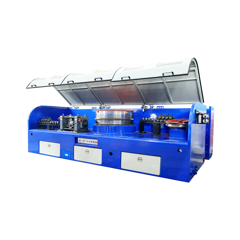
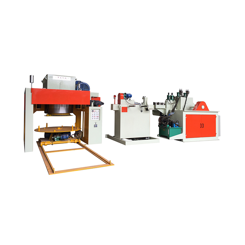
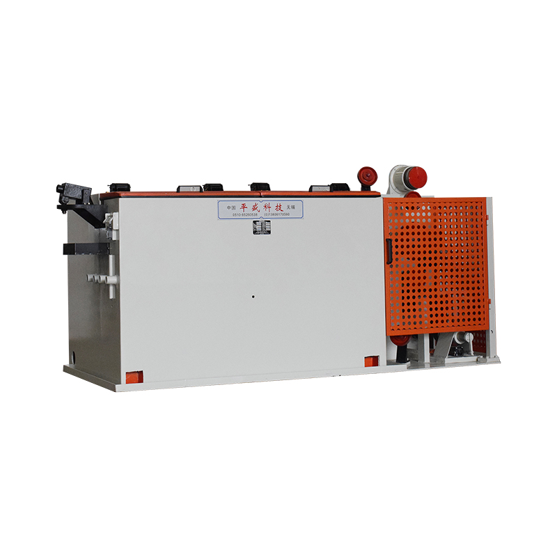
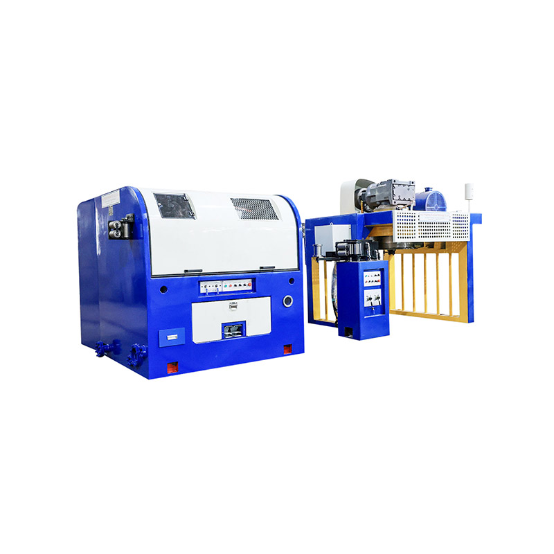
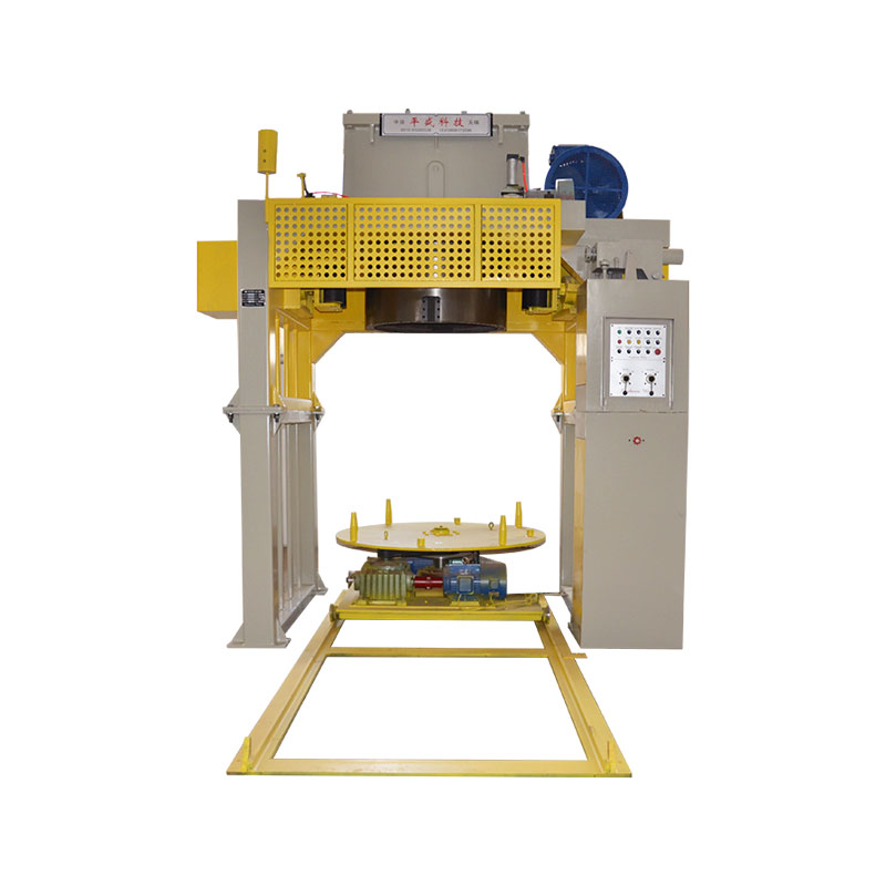
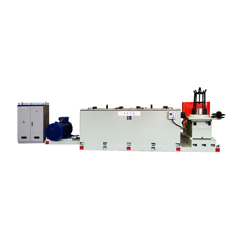
A typical wire drawing machine consists of several interconnected components working together to reduce wire diameter accurately and consistently.
- Payoff reel: holds and unwinds the incoming raw wire or rod
- Drawing dies: precision-machined tools that progressively reduce wire diameter
- Capstans or bull blocks: rotating drums that pull the wire through each die
- Lubrication system: delivers coolant and lubricant to reduce friction and heat
- Take-up reel: collects the finished, reduced-diameter wire
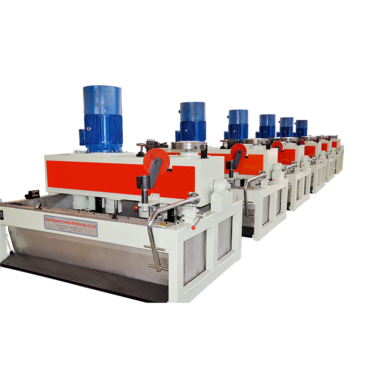
The number of dies and capstans varies depending on the machine design and the total diameter reduction required, with multi-die machines capable of drawing wire through several progressively smaller dies in a single continuous pass.
Step-by-Step Breakdown of the Wire Drawing Process
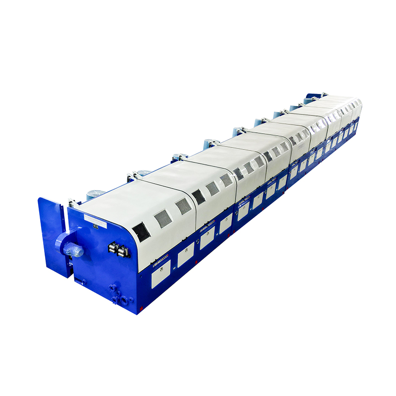
While specific setups vary by machine type and application, the core wire drawing process generally follows a consistent sequence of stages.
Material Preparation
Before drawing begins, the raw wire rod is typically cleaned to remove surface scale, rust, or oxidation through a process called pickling, which uses acid baths to strip away contaminants that could damage the drawing dies or compromise the finished wire's surface quality.
Pointing the Wire
The leading end of the wire rod is mechanically tapered or "pointed" to a smaller diameter so it can be threaded through the first drawing die and gripped by the capstan, initiating the pulling process.
Drawing Through the Die Sequence
The wire is pulled through each die in sequence, with each pass reducing the diameter incrementally. The amount of reduction per pass is carefully calculated, since attempting too large a reduction in a single pass can cause the wire to break or develop internal defects.
Lubrication and Cooling
Throughout the drawing process, lubricant is continuously applied to reduce friction between the wire and the die surface, which helps prevent excessive heat buildup and reduces wear on the dies themselves. Without adequate lubrication, friction-generated heat can compromise both the wire's surface finish and the die's operational lifespan.
Annealing Between Passes
Because drawing work-hardens the metal, making it progressively stronger but also more brittle with each pass, wire often requires intermediate annealing, a controlled heating and cooling process that restores ductility and allows further drawing without cracking.
Types of Wire Drawing Machines
Manufacturers choose between different machine configurations depending on production volume, wire diameter range, and material type.
| Machine Type | Description | Typical Application |
| Single-Block Drawing Machine | One die and capstan per pass | Small-scale or specialty production |
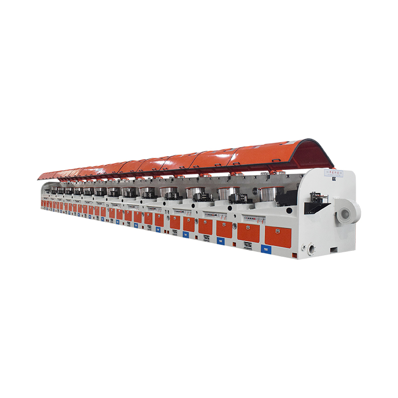
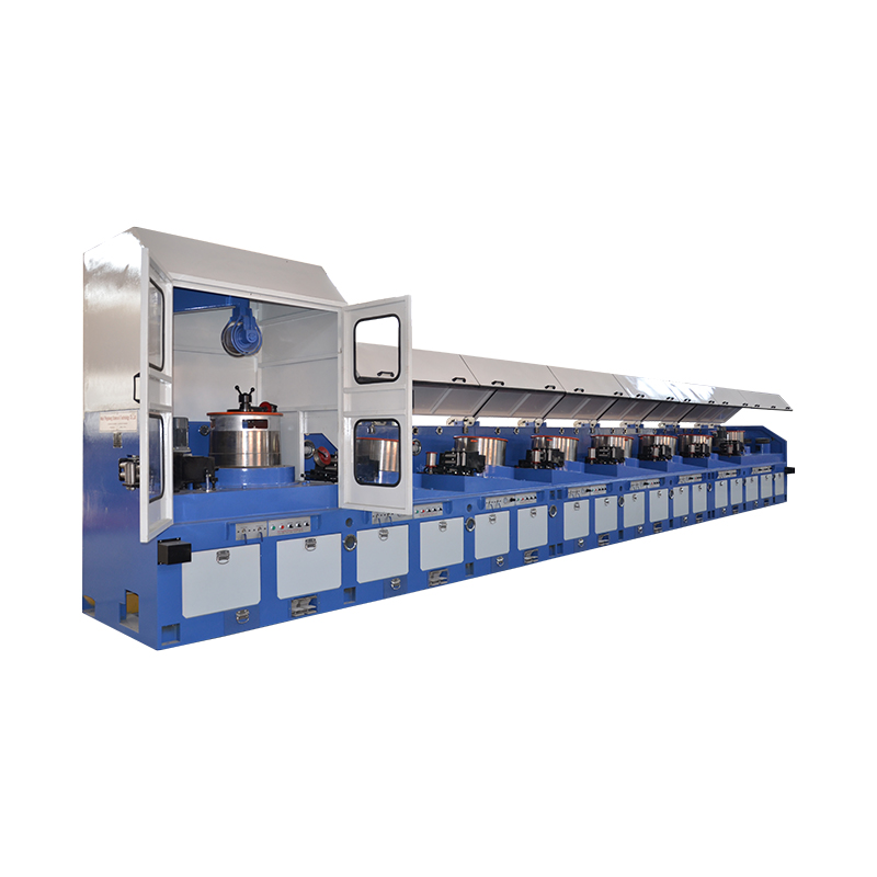
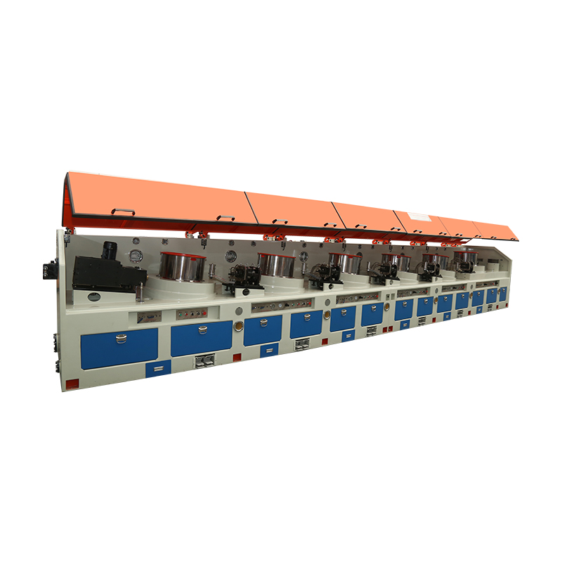
| Multi-Die Continuous Machine | Multiple dies in sequential line | High-volume industrial wire production |
| Bull Block Machine | Uses rotating drums to pull wire | Heavier gauge wire and cable |
| Fine Wire Drawing Machine | High-speed, precision dies | Fine electrical and electronic wire |
Multi-die continuous machines dominate large-scale industrial wire production because they can process wire through numerous diameter reductions in a single continuous operation, significantly increasing throughput compared to single-block systems that require manual repositioning between passes.
Factors That Affect Wire Quality During Drawing
Several variables during the drawing process directly influence the mechanical properties and surface quality of the finished wire.
Die Material and Condition
Drawing dies are typically made from tungsten carbide or, for higher-volume production, polycrystalline diamond, since these materials resist the abrasive wear caused by constant contact with the wire. Worn or damaged dies produce wire with inconsistent dimensions and poor surface finish.
Drawing Speed
Faster drawing speeds increase production output but also generate more heat and friction, which can affect wire surface quality if not properly managed through adequate lubrication and cooling systems.
Reduction Ratio per Pass
The percentage reduction in cross-sectional area at each die must be carefully calculated based on the material's properties. Excessive reduction in a single pass increases the risk of wire breakage and can introduce internal stress defects that weaken the finished product.
Common Materials Processed Through Wire Drawing
Wire drawing machines process a range of metals, each requiring specific adjustments to drawing speed, lubrication, and annealing schedules based on the material's inherent ductility and work-hardening characteristics.
- Copper: widely used in electrical wiring due to excellent conductivity and ductility
- Steel: used in construction, springs, and reinforcement applications
- Aluminum: valued for lightweight electrical and structural applications
- Stainless steel: chosen for corrosion-resistant wire products
Copper and aluminum generally draw more easily than steel due to their higher natural ductility, requiring less frequent intermediate annealing during the reduction process compared to harder ferrous metals.
Optimizing Wire Drawing for Better Production Outcomes
Manufacturers looking to improve wire drawing efficiency and product quality typically focus on a combination of equipment maintenance and process control. Regularly inspecting and replacing worn dies prevents dimensional inconsistencies from accumulating across production runs, while monitoring lubricant quality and application rates helps maintain consistent friction control throughout the drawing sequence.
Implementing proper annealing schedules based on the specific reduction ratios being achieved also plays a significant role in preventing wire breakage and ensuring the finished product meets required tensile strength and ductility specifications. By understanding each stage of the wire drawing process and the variables that influence outcomes, manufacturers can better calibrate their equipment and procedures to produce consistent, high-quality wire suited to their specific industrial applications.