
 EN
EN
 English
 Español
 Français
 Português
 عربى
عربىUnderstanding the Wet Wire Drawing Machine: Why It Matters Globally
Content
- 1 What Is a Wet Wire Drawing Machine?
- 2 Core Components and How They Work Together
- 3 Wet vs. Dry Wire Drawing: Key Differences
- 4 Materials Processed on Wet Wire Drawing Machines
- 5 Global Industries That Depend on Wet Wire Drawing
- 6 Factors to Consider When Selecting a Wet Wire Drawing Machine
- 7 Maintenance Practices That Extend Machine Life
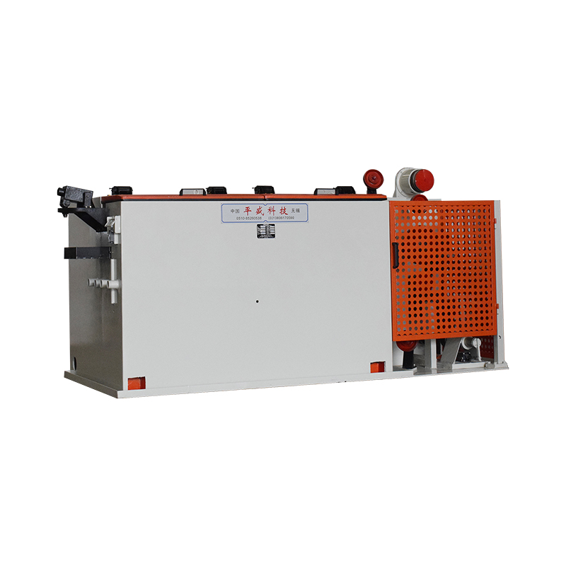
The wet wire drawing machine is a cornerstone of modern wire manufacturing. Used across industries ranging from automotive and electronics to construction and telecommunications, this machine enables the production of ultra-fine wire with exceptional surface quality, dimensional accuracy, and mechanical consistency. As global demand for high-performance wire products continues to grow, understanding how wet wire drawing machines function — and why they differ from other drawing methods — becomes increasingly important for manufacturers, engineers, and procurement specialists alike.
What Is a Wet Wire Drawing Machine?
A wet wire drawing machine is a type of metalworking equipment designed to reduce the diameter of wire by pulling it through a series of progressively smaller dies. What sets it apart from dry drawing machines is the continuous application of liquid lubricant — typically an emulsion or oil-based coolant — directly onto the wire and dies throughout the entire drawing process. This lubrication is not merely a convenience; it is a functional necessity that makes fine and ultra-fine wire production possible.
The machine is primarily used to draw wire down to very small diameters, often ranging from 0.1 mm to 2.0 mm, although advanced systems can achieve diameters as fine as 0.01 mm or less. These fine wires are used in applications where precision and surface cleanliness are non-negotiable, such as in medical devices, precision electronics, high-tension cables, and tire reinforcement cords.
Core Components and How They Work Together
Understanding the machine starts with its major components. Each part plays a specific role in ensuring that the wire is reduced smoothly, consistently, and without surface damage or internal stress concentration.
Drawing Dies
The dies are the heart of the machine. Made from polycrystalline diamond (PCD) or tungsten carbide, each die has a precisely machined conical entry zone, a reduction angle, a bearing zone, and an exit relief. The wire is pulled through a sequence of dies — commonly 15 to 25 individual dies in a single pass — with each die reducing the wire's cross-sectional area by a controlled percentage known as the reduction ratio. PCD dies are preferred for fine wire applications because they maintain shape accuracy longer and generate less friction than carbide dies.
Capstans and Spools
Between each die, rotating capstans grip and advance the wire while maintaining constant tension. The capstans are motor-driven and precisely synchronized to ensure the wire does not stretch unevenly or break between stages. After the final die, the finished wire is collected onto a take-up spool at speeds that can exceed 20 meters per second in high-speed systems, depending on wire gauge and material.
Lubrication and Cooling System
The liquid lubricant is continuously circulated over the wire and through the die boxes. It performs three critical functions simultaneously: reducing friction between the wire and die surface, dissipating heat generated by plastic deformation of the metal, and flushing away metallic fines and debris that could scratch or contaminate the wire surface. The lubricant is filtered, temperature-controlled, and recirculated through a closed-loop system to maintain consistent concentration and cleanliness.
Control and Drive Systems
Modern wet wire drawing machines are equipped with programmable logic controllers (PLCs) and variable frequency drives (VFDs) that regulate the speed of each capstan independently. This allows operators to fine-tune tension distribution across the drawing sequence, compensate for material inconsistencies, and minimize wire breakage. Advanced systems also incorporate real-time monitoring of wire diameter, surface quality, and lubricant parameters.
Wet vs. Dry Wire Drawing: Key Differences
Both wet and dry wire drawing machines reduce wire diameter through dies, but the operating principles and suitable applications differ significantly. Choosing the wrong method for a given application results in poor surface quality, increased die wear, or wire breakage.
| Feature | Wet Drawing Machine | Dry Drawing Machine |
| Lubrication Type | Liquid emulsion or oil | Dry soap or powder |
| Wire Diameter Range | 0.01 mm – 2.0 mm | 0.5 mm – 12 mm+ |
| Drawing Speed | High (up to 25+ m/s) | Moderate |
| Surface Quality | Excellent, clean finish | Good, may have soap residue |
| Heat Dissipation | Superior (liquid cooling) | Limited |
| Typical Materials | Steel, copper, stainless, alloy | Aluminum, medium carbon steel |
The liquid lubrication used in wet drawing allows for much higher drawing speeds, significantly lower die temperatures, and superior wire surface cleanliness. This makes wet drawing the only viable method when producing fine wire for applications that demand tight dimensional tolerances and a defect-free surface finish.
Materials Processed on Wet Wire Drawing Machines
Wet wire drawing machines are highly versatile and can process a wide range of metallic materials, provided the correct lubricant formulation and die geometry are used for each material type. The most commonly processed materials include:
- High-carbon steel: Used for tire bead wire, spring wire, and rope wire. Requires careful control of drawing tension and intermediate annealing to prevent work hardening beyond the material's ductility limits.
- Stainless steel: Commonly drawn into wire for medical instruments, filter mesh, and food-grade conveyor components. Stainless steel work-hardens rapidly, requiring lower reduction ratios per pass and more frequent annealing cycles.
- Copper and copper alloys: Widely used in electrical wiring, data cables, and connectors. Copper's ductility allows for high reduction ratios per pass, making wet drawing highly efficient for copper conductor production.
- Nickel and nickel alloys: Used in heating elements, resistance wire, and aerospace components. These materials require specialized lubricants and die materials due to their abrasive nature and work-hardening behavior.
- Precious metals: Gold, silver, and platinum wires used in medical devices, electronics, and jewelry are frequently produced on high-precision wet drawing machines with extremely tight tolerances.
Global Industries That Depend on Wet Wire Drawing
The global demand for fine and ultra-fine wire products is driven by technological advancement across multiple sectors. Wet wire drawing machines sit at the center of this supply chain, enabling the precision wire required for modern applications.
Automotive and Tire Manufacturing
The automotive industry is one of the largest consumers of fine steel wire globally. Tire bead wire, steel cord for radial tires, and brake cable wire are all produced using wet drawing processes. A single passenger tire contains between 1.0 and 1.5 kg of high-tensile steel cord drawn to diameters as fine as 0.15 mm. As electric vehicles require lighter and stronger tire constructions, demand for precision-drawn tire cord continues to grow.
Electronics and Telecommunications
Bonding wires used in semiconductor packaging, fine copper conductors for data cables, and precision resistance wires in electronic components all require wet drawing. As consumer electronics continue to miniaturize and data transmission speeds increase, the specifications for conductor wire become increasingly stringent. Fine copper wire with diameters below 0.05 mm is routinely produced on modern multi-die wet drawing machines for these applications.
Medical Devices and Surgical Instruments
Medical-grade wire used in guidewires, stents, surgical sutures, and orthodontic appliances demands biocompatible materials and flawless surface quality. Stainless steel and nitinol wires for medical applications are drawn in wet conditions to achieve the required surface cleanliness and dimensional consistency that patient safety requires. Regulatory standards such as ISO 13485 impose strict traceability and quality documentation requirements on this supply chain.
Construction and Infrastructure
Pre-stressed concrete strands, bridge cables, and suspension ropes are made from high-carbon steel wire drawn on heavy-duty wet machines. These wires must meet strict tensile strength and fatigue resistance standards because structural failure in infrastructure applications can be catastrophic. The construction of modern suspension bridges and long-span roof structures depends on wire produced with the consistency and quality that only wet drawing machines can reliably deliver at scale.
Factors to Consider When Selecting a Wet Wire Drawing Machine
Purchasing or upgrading a wet wire drawing machine is a significant capital investment that requires careful evaluation of production requirements, material specifications, and long-term operating costs. The following factors should guide the decision-making process:
- Target wire diameter and reduction ratio: Machines are engineered for specific diameter ranges. A machine designed for 0.3–2.0 mm applications will not deliver optimal results when used to produce wire at 0.05 mm. Specify the full range of diameters required before evaluating equipment.
- Number of drawing dies: More dies per pass allow for greater total reduction from input to output diameter without intermediate annealing, improving production efficiency. Standard configurations range from 12 to 25 dies, while specialized fine wire machines may have more.
- Drawing speed and motor power: Higher drawing speeds increase output but generate more heat and require more sophisticated lubrication and tension control systems. Matching motor power to material ductility and target speed is critical to operational stability.
- Lubricant management system: A well-designed filtration, concentration monitoring, and temperature control system for the drawing lubricant directly impacts die life, wire surface quality, and maintenance frequency. This is often an underestimated factor in total cost of ownership.
- Automation and monitoring capabilities: Machines equipped with automatic wire breakage detection, remote diagnostics, and production data logging reduce labor requirements and enable proactive maintenance, which is especially valuable in high-volume production environments.
Maintenance Practices That Extend Machine Life
Consistent maintenance is essential for keeping a wet wire drawing machine operating at peak efficiency and minimizing unplanned downtime. The dies should be inspected regularly for wear, ovality, and surface degradation using optical comparators or digital gauging tools. Die replacement schedules should be based on measured dimensional drift, not just visual inspection, since subtle die wear can cause wire diameter variation that leads to downstream quality rejections.
The lubricant system requires daily monitoring of concentration, pH, and contamination levels. Lubricant that is too dilute will cause increased die wear and wire surface scratching, while lubricant that is too concentrated may leave residue on the wire surface that affects downstream processes such as plating, coating, or welding. Capstan surfaces should be checked for grooving, and drive systems should be calibrated periodically to ensure tension profiles remain within specified parameters. A structured preventive maintenance program, combined with operator training, is the most cost-effective approach to maximizing the productive life of this equipment.


